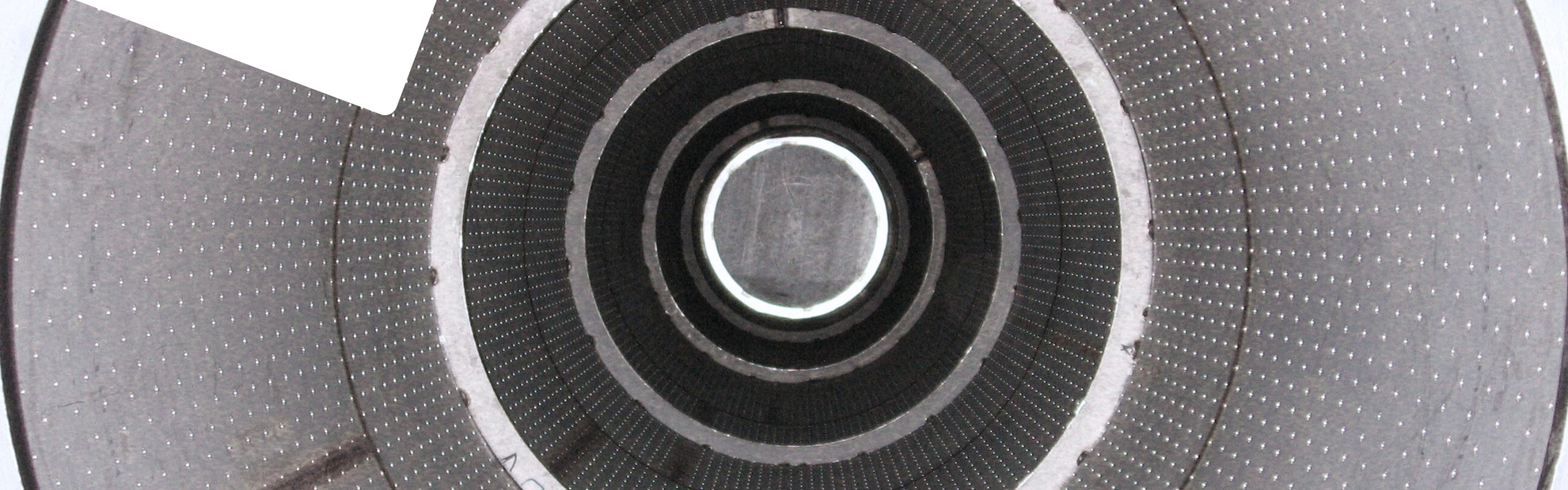
To ensure no pressure drop built-up after operating over cycle run, flow restriction need to be reduced by the high open area of wedge wire screen
The precision machining of the components ensures a tight fit.
Application: Gas sweetening, gas drying, sulphur removal, hydrotreating, hydrocracking, hydrogenation, etc.
Design based on your application
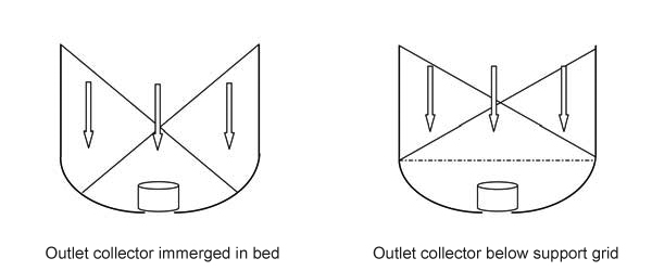
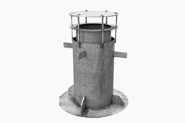
In the standard downflow pattern, the outlet collector is either concealed within an immersed ball bed filling the bottom of the reactor or located beneath a support grid that distributes or collects flow. In the latter case, the outlet collector can also be designed as a safety retention device to contain catalyst leakage.
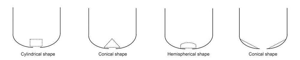
The design of the outlet collector can vary based on the vessel’s bottom head, process conditions, and fluid dynamics. While the cylindrical shape is the most commonly used, conical and hemispherical shapes are also viable options. Design considerations, such as catalyst unloading nozzles or access openings for cleaning, are often required and influence the outlet collector's design. To enhance upstream flow, features like controlled open areas and deflectors are incorporated, with the goal of achieving as uniform a flow distribution as possible.
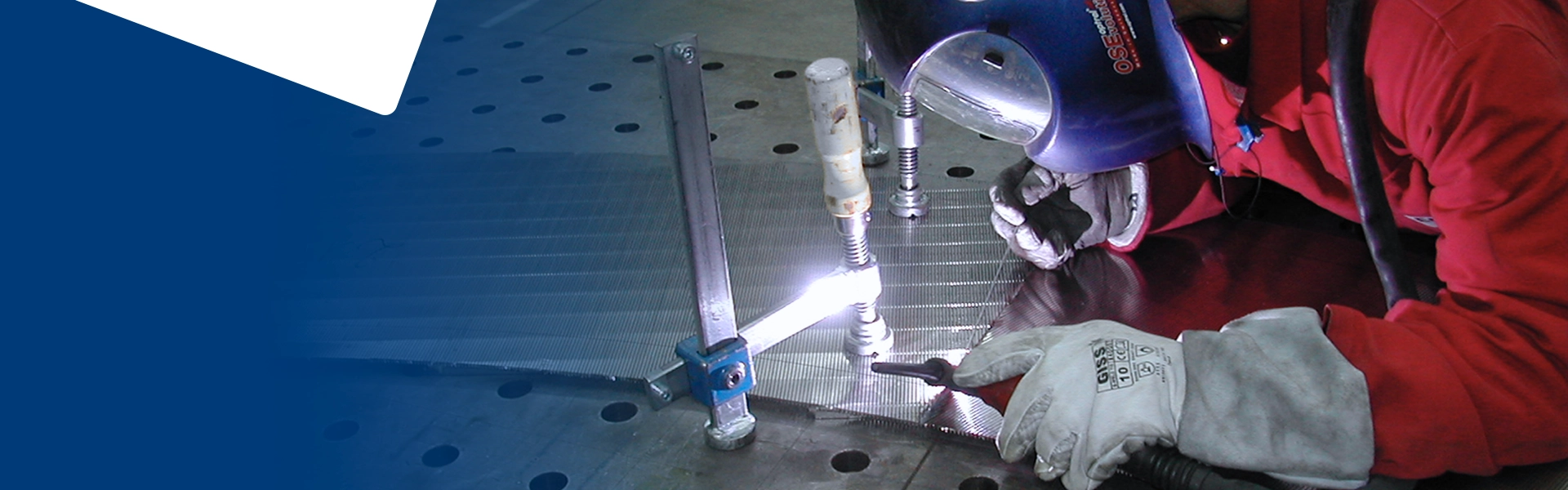
The connection to the vessel head must align with the shell shape to ensure a proper seal. The outlet collector is supported by either a machined support or a centering ring. A locating sleeve can be used to position the assembly and prevent direct contact between the nozzle weld and hot gases.
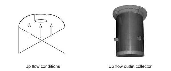
Outlet collectors are typically installed in sectors that pass through the vessel manway. During reverse regeneration or standard upflow operation, the outlet collector is positioned below the top vessel nozzle, operating in the opposite direction to the feed diffuser. To prevent catalyst loss due to bed fluidization or potential catalyst entrainment, the design includes features to retain the catalyst. Additionally, the same design elements are applied to ensure effective sealing.
Design Parameters
Process parameters:
Key process parameters include design and operating temperature, pressure drop through the catalyst, nozzle size, opening size, and percentage of open area. Additional conditions, such as changes in flow direction and process cycles, are necessary to determine the type and size of the outlet collector.
Mechanical parameters:
The necessary reinforcement is defined by mechanical requirements such as manhole size, the weight of the catalyst and ceramic balls, and the corrosion allowance.


 Feed Diffuser
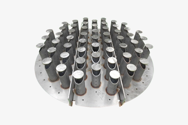 Liquid Distributor Tray
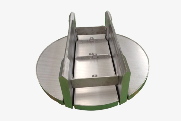 Support Grid
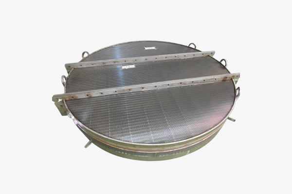 Outlet Collector
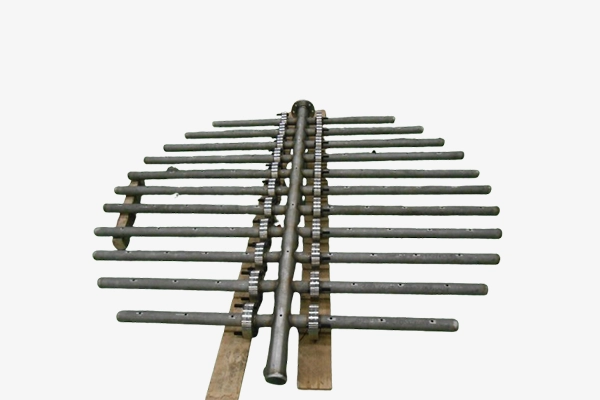 Quench System
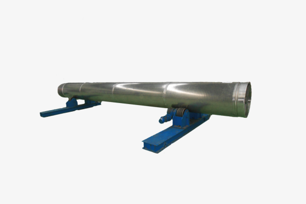 Center Pipe
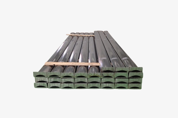 Scallops
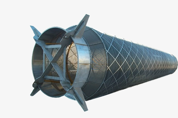 Outer Basket
.png) Disc Filter
Disc Filter.jpg) Polycrystalline silicon hydrogenation reactor internals
Polycrystalline silicon hydrogenation reactor internals Scallops for Xylene Isomerization Unit
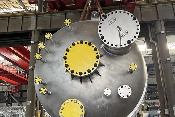 Carbonyl Synthesis Reactor System
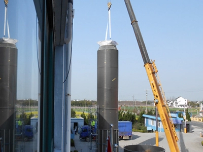 Center Pipes for Aromatics Unit