

Related Products
-
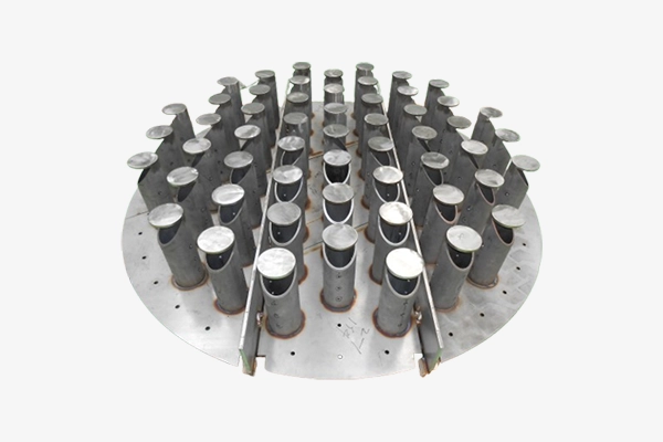
 Feed Diffuser
 -
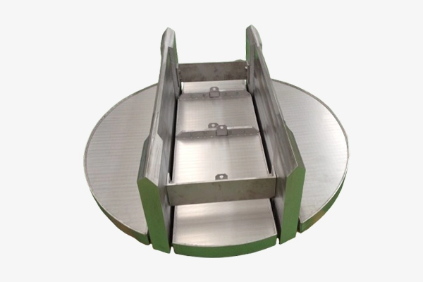
 Liquid Distributor Tray
 -
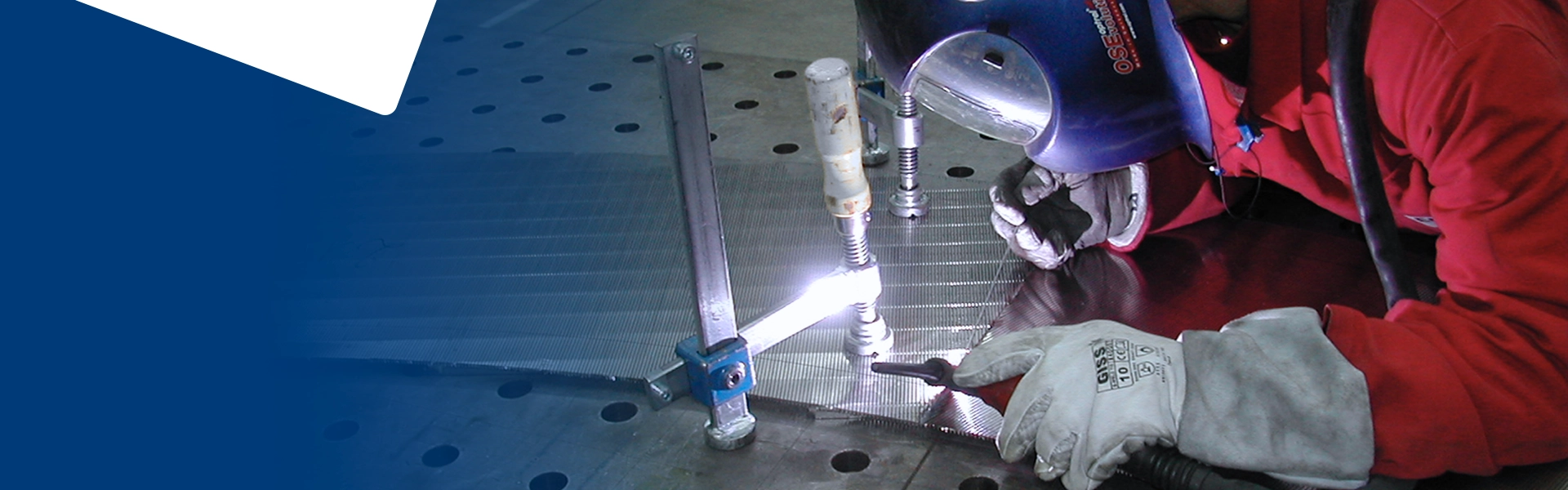
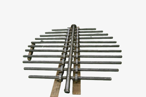
 Support Grid
 -
 Outlet Collector
 -
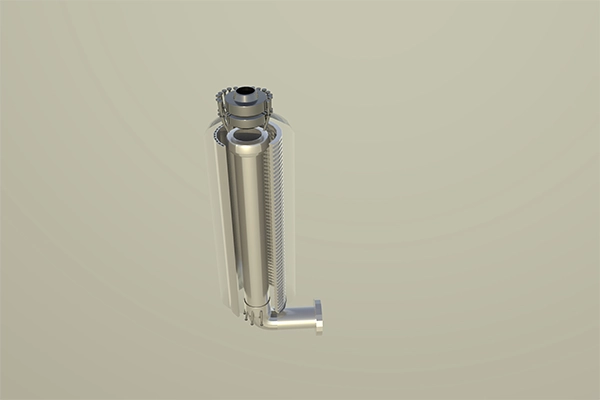
 Quench System
 -
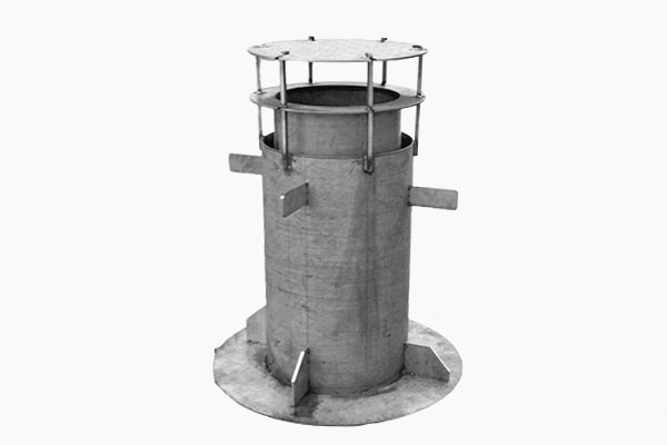
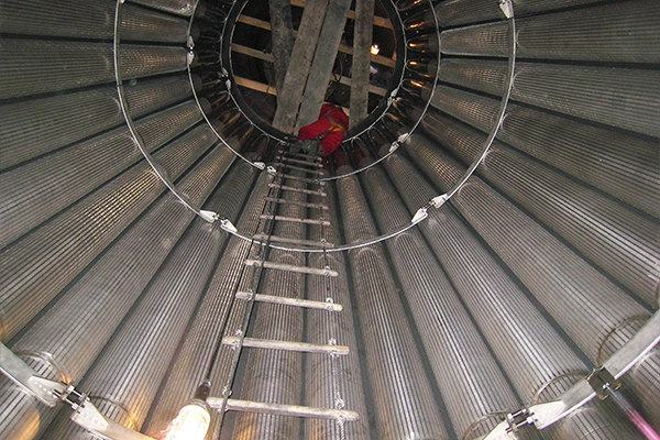
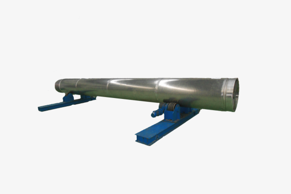 Center Pipe
 -
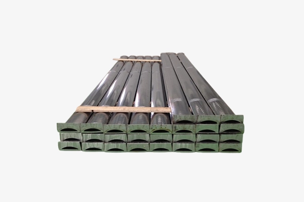 Scallops
 -
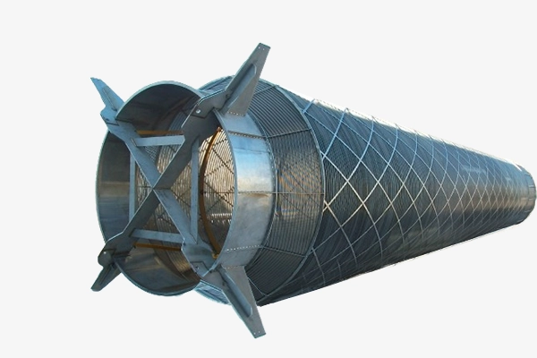 Outer Basket
 -
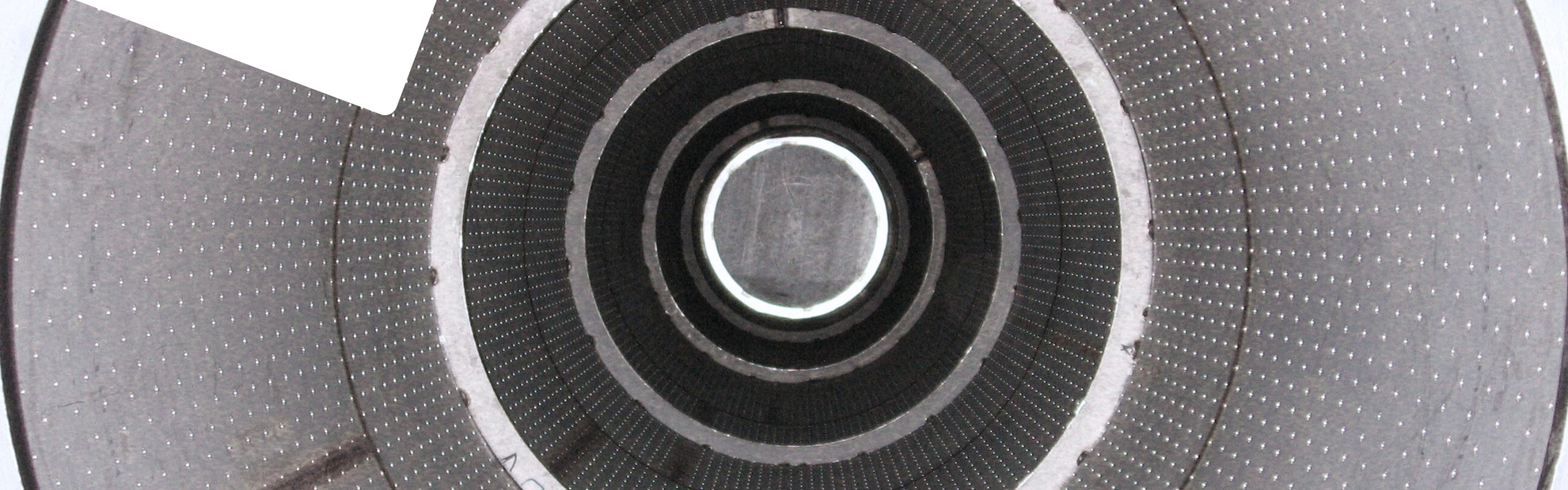
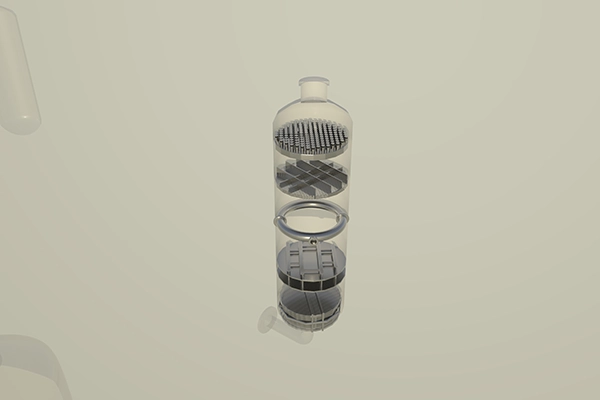
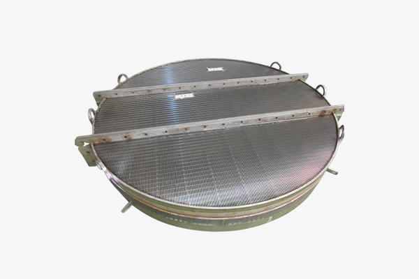
.png) Disc Filter
Disc Filter -
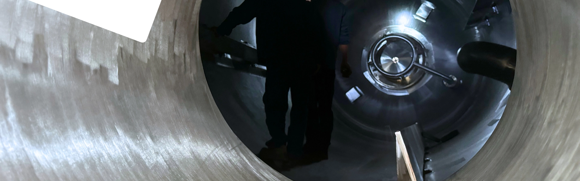
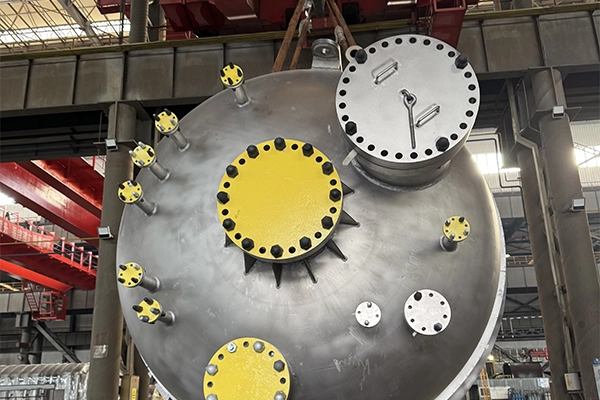
.jpg) Polycrystalline silicon hydrogenation reactor internals
Polycrystalline silicon hydrogenation reactor internals
Related Appliaction
-
 Scallops for Xylene Isomerization Unit
 -
 Carbonyl Synthesis Reactor System
 -
 Center Pipes for Aromatics Unit
3153-3 Lvxiang Village, Jinshan District, Shanghai
No.1, Sanqiang Road, Rugao City, Jiangsu
Tel: +86 13651755429;+86 13916961821
Email: ys.zhu@ekaislot.com;zsy@ekaislot.com
Quick Links
Products
Contact Now
copyrights © Ekaislot
Website Support: Mingxin