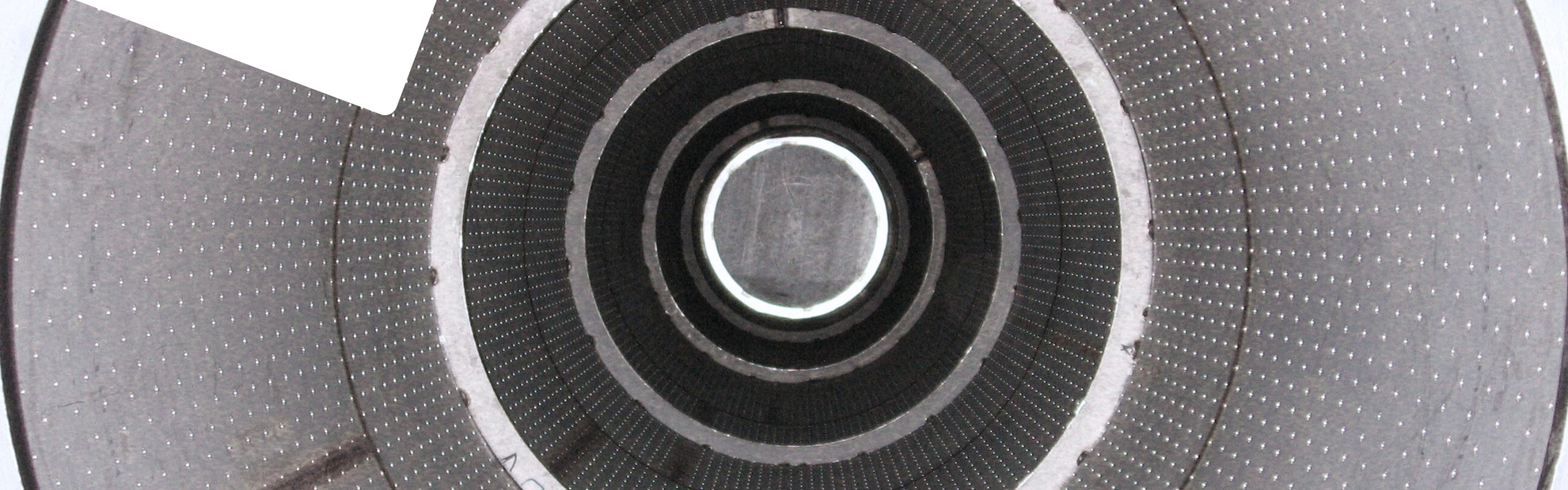
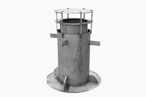
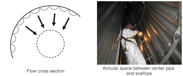
The center pipes inside the radial flow reactors are used for flow collection or distribution. They are Scallops inside the radial flow reactors are for flow collection or distribution.
It is generally D-shape, extending parallel to the inner vessel wall,and its inner layer delimits the outer layer of the catalyst bed.
The mechanical design of the equipment considers the loads generated in operation.
After defects being revealed in field tests and feedback being given during the transitional heating, cooling and regeneration stages, the design is correspondingly enhanced.
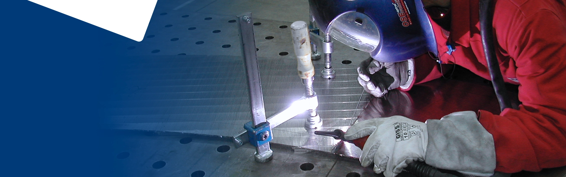
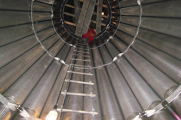
The verticality and straightness of the outer basket are measured by laser, and the roundness is controlled within a certain error range.
Application: Continuous Catalytic reforming (CCR) unit.
Design based on your application
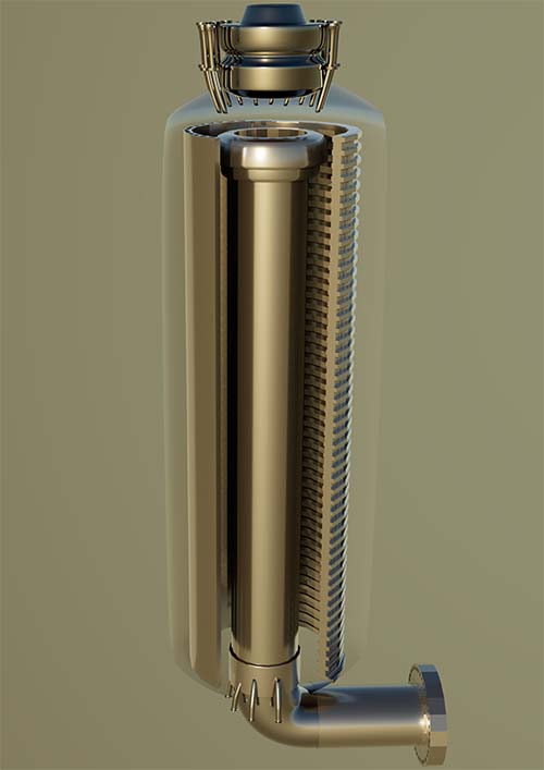
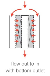
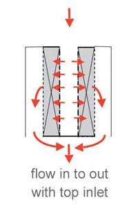
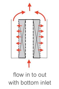
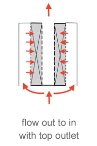
The cover deck closes the gap between the internal screen component and the scallop. The flow direction could be outward or inward.
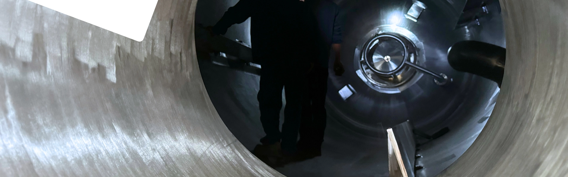
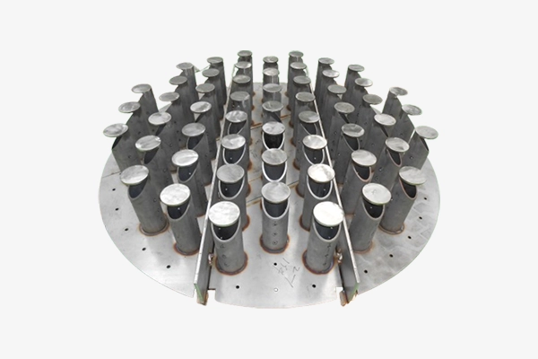
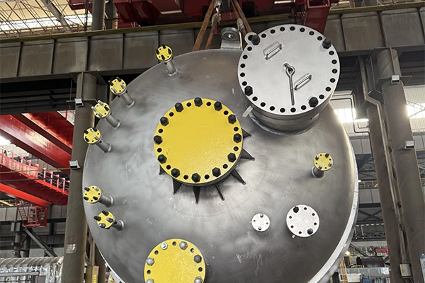
Scallops are typically installed through the vessel's top manhole, mounted on a support ring attached to the vessel wall.
These hollow structures distribute and collect gas flow across their inner surface. Each scallop is positioned next to the others, forming a set. The flow rate through each scallop is proportional to its cross-sectional area, with the total reactor capacity being the sum of all individual scallop flow rates.
To prevent hot spots on the vessel shell during high-temperature operation, refractory or liner materials may be applied to the shell for additional protection.
Design Parameters
Process parameters:
The gas flow rate and pressure drop through the catalyst are key process conditions used to determine the scallops' inner diameter, length, cross-section, and, if applicable, the perforation percentage in the distribution system.
Mechanical parameters:
Catalyst weight, axial and radial loads, and design temperature are essential factors for defining the required mechanical reinforcement.